
 Magic Bytes
Magic Bytes
Magic Bytes
Magic Bytes
Magic Bytes
Magic Bytes
Magic Bytes
The version of Scratch included with the Raspberry Pi has a number of unique features; one of the most useful is its ability to communicate with the GPIO pins (General Purpose Input Output). These pins allow you to connect your Raspberry Pi to a range of devices, from lights and motors to buttons and sensors.
By completing this resource you will learn:
One powerful feature of the Raspberry Pi is the row of GPIO pins along the top edge of the board. GPIO stands for General-Purpose Input/Output. These pins are a physical interface between the Raspberry Pi and the outside world. At the simplest level, you can think of them as switches that you can turn on or off (input) or that the Pi can turn on or off (output).
The GPIO pins allow the Raspberry Pi to control and monitor the outside world by being connected to electronic circuits. The Pi is able to control LEDs, turning them on or off, run motors, and many other things. It’s also able to detect whether a switch has been pressed, the temperature, and light. We refer to this as physical computing.
There are 40 pins on the Raspberry Pi (26 pins on early models), and they provide various different functions.
If you have a RasPiO pin label, it can help to identify what each pin is used for. Make sure your pin label is placed with the keyring hole facing the USB ports, pointed outwards.

You’ll see pins labelled as 3V3, 5V, GND and GP2, GP3, etc:
| 3V3 | 3.3 volts | Anything connected to these pins will always get 3.3V of power |
| 5V | 5 volts | Anything connected to these pins will always get 5V of power |
| GND | ground | Zero volts, used to complete a circuit |
| GP2 | GPIO pin 2 | These pins are for general-purpose use and can be configured as input or output pins |
| ID_SC/SD | Special purpose pins |
WARNING: If you follow the instructions, then playing about with the GPIO pins is safe and fun. Randomly plugging wires and power sources into your Pi, however, may destroy it, especially if using the 5V pins. Bad things can also happen if you try to connect things to your Pi that use a lot of power; LEDs are fine, motors are not.
You can test whether your GPIO pins and LEDs are working by building the circuit below. You can use any resistor over about 50Ω.
The LED is connected directly to the GND pin and the 3V3 pin via the 330 Ohm resistor, and should light up.
Be sure to connect your LED the correct way round; the longer leg should be connected to the 3V3 pin:

To control the LED, you’ll need to adapt your circuit to use a switchable pin.
In the diagram below pin 17 has been used, but you can use any numbered pin you wish.

![]()

when GreenFlag clickedblock onto the scripts area:
Scratch uses broadcast blocks to communicate with the GPIO pins; the first broadcast you need is gpioserveron which activates the GPIO functionality:

As your GPIO pin can be used as either input or output, you’ll need to specify in which mode your pin is being used with the config17out broadcast:

From this point on, you can control your LED using two broadcasts: gpio17high to turn it on and gpio17low to turn it off. Using these two messages and some pauses, you can make an LED flash continuously:

As well as controlling the physical world, you can react to it using an input device such as a button.
Connect your button to a breadboard, then connect one pin to a ground pin and the other to a numbered GPIO pin. In this example pin 2 has been used:

Before Scratch can react to your button, it needs to be told which pin is configured as an input pin.
Assuming you have started a new Scratch file, you’ll also need to start the GPIO server. The following code will configure pin 4 as an input:

Once you have built the code above, you need to click the green flag in order for it to run and for your pin to be set up.
Next, you need to go to the Sensing menu in Scratch:

From here you need to find the block and click the triangle to reveal a menu. Select gpio2 from the menu and click the tickbox to the left:

You should now see the current state of the pin in the stage area:

Now when you press your button, the state should change from 1 to 0.
Now that your button is all set up and working, you can make it do something. You can start off by making it control a sprite.
Begin with a forever loop with an if block inside it. This will continually check the if condition and perform some action if the condition is met. The action in the example below will make the current sprite say “Hello!”:

Finally, to make this work you need to add the condition, which is that we want the sprite to speak when the button value = 0:

If everything is correct, your button should make the sprite speak.
To finish off, you can combine your two programs so that the button can turn the LED on and off.
Adapt your script and use an If Else block so that it looks like the example below:

Now when you push the button, the LED should light up.
There are two main types of buzzer: active and passive.
A passive buzzer emits a tone when a voltage is applied across it. It also requires a specific signal to generate a variety of tones. The active buzzers are a lot simpler to use, so these are covered here.
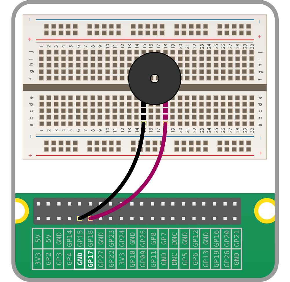
An active buzzer can be connected just like an LED, but as they are a little more robust, you won’t be needing a resistor to protect them.
Set up the circuit as shown below:
Now you can sound the buzzer by using the code below:

Or even make the buzzer beep:

Humans and other animals emit heat all the time.
A PIR sensor detects changes in the amount of IR radiation (heat) it receives. When there is a change, then a pulse is triggered. This means that a PIR sensor can detect when a human (or any animal) moves in front of it.

The pulse emitted when a PIR detects motion needs to be amplified, and so it needs to be powered. There are three pins on the PIR; they should be labelled Vcc, Gnd, and Out. If these labels aren’t clear, they are sometimes concealed beneath the Fresnel lens (the white cap), which you can temporarily remove to see the pin labels.
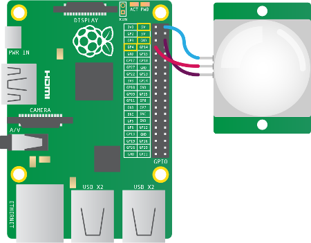
Vcc pin needs attaching to a 5V pin on the Raspberry Pi.Gnd pin on the PIR sensor can be attached to any ground pin on the Raspberry Pi.Out pin needs to be connected to any of the GPIO pins.Our version of Scratch on Raspbian is extra special. It allows you to access and control the GPIO pins.
Click on control in the top-left display. Drag the block onto the scripts area.
Drag a broadcast block to your scripts area and attach it to theblock. Click on the drop-down menu on the broadcast block and select new.
Type config4in in the message name box. This instruction will tell the Raspberry Pi to set GPIO pin 4 as an input.

Press the green flag in the upper-right corner of the Scratch window. This executes the instruction to set GPIO pin 4 as an input.
Scratch uses the ‘Sensing’ blocks to check if there is any input on the GPIO pins. If there is an input, the value of the pin changes from 0 to 1. As you connected the PIR sensor to GPIO pin 4 of the Pi, we need to monitor that. Click on the drop-down menu on the sensor value block and choose gpio4.
Tick the checkbox to the left of the block to display the pin value on screen.

Test the PIR sensor by waving your hand in front of it. When it detects movement, the value on the screen should change from 0 to 1.
If the value doesn’t change, check that the correct pins are connected.
For this worksheet you’ll need a breadboard, three LEDs, a button, a buzzer, and the necessary jumper cables and resistors. You can purchase these individually, or get everything you need in the CamJam EduKit.
To get started, you’ll need to place all the components on the breadboard and connect them to the Raspberry Pi.
First, you need to understand how each component is connected:
To save on using 5 different ground pins, you can just plug a single GND pin into the negative row on a breadboard. This is called a common ground.
Place the components on the breadboard and connect them to the Raspberry Pi GPIO pins, as shown below:
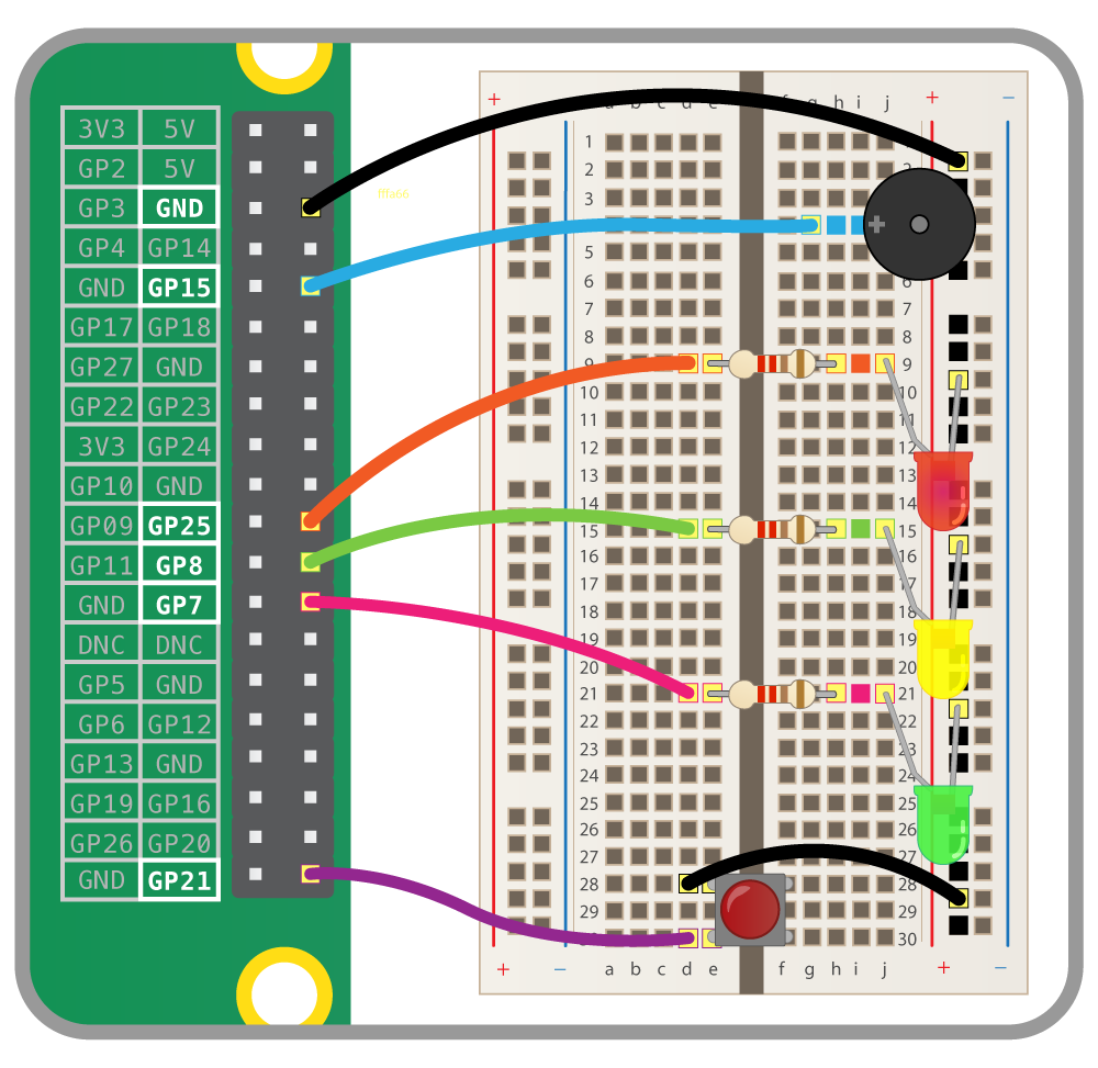
This table shows which GPIO pin is connected to which component, in case you get lost:
| Component | GPIO pin |
|---|---|
| Button | 21 |
| Red LED | 25 |
| Amber LED | 8 |
| Green LED | 7 |
| Buzzer | 15 |
Open Scratch and save a new file.
The first step is to configure all the GPIO pins, so that they are set to be inputs and outputs. Use broadcast blocks, as shown below:

Now use another when greenflag clicked block to set a variable called pushed to False when the script starts:

Now use a forever loop to wait for the button to be pushed:

And finally, you can change the value of the pushed variable to True if the button is pushed:

Now you can create a basic traffic light sequence. The sequence for traffic lights is Red–>Red/Amber–>Green–>Amber, and constantly repeated. This is the perfect excuse for a loop.
The script below will create your basic traffic light sequence:

Test out the light sequence by clicking the greenflag.
You want to be able to interrupt the sequence when the button is pushed, to allow a pedestrian to cross the road. An if/else block will help with this:

Test out the sequence, and then try pushing the button. The traffic light sequence should finish and then stop.
To help the visually impaired, a crossing normally beeps when it is safe to cross.
beep. The first thing it should do is make sure the light is red:
repeat block to switch the buzzer on and off a few times:
pushed variable back to False:
broadcast beep and wait when the button has been pushed:
Published by Raspberry Pi Foundation under a Creative Commons license.
View project & license on GitHub